Logitech G25/G27 shifter/pedals adapter to use as standalone device
Buy Parts
| References | Qty | Description | Manufacturer | MPN | Digikey | Mouser | RS | Newark | Farnell |
|---|---|---|---|---|---|---|---|---|---|
| 25/27 | 1 | 90131-0123 | WM8121-ND | 538901310123 | 6703443 | 60H4442 | 2381222 | ||
| BOOT0 | 1 | 90131-0122 | WM8120-ND | 538901310122 | 6703449 | 25M5898 | 1756986 | ||
| C1-C2 | 2 | 22pF,0603 | C0603C220J1GACTU | 399-7874-2-ND | 80C0603C220J1G | 8015350 | 75R1532 | 1813429 | |
| C3-C4 | 2 | 100nF,0603 | C0603C104K5RACTU | 399-5089-2-ND | 80C0603C104K5R | 8015347 | 72J5992 | 1692286 | |
| C5 | 1 | 4.7uF,0603 | CL10A475KL8NRNC | 1276-6794-6-ND | 81GRM188R60J475ME9D | 6911155 | 62W5999 | 2211163 | |
| C6 | 1 | 10nF,0603 | C0603C103J5JAC7867 | 399-13384-1-ND | 810C1608X7R1H103K | 7882988 | 45Y5166 | 2470427 | |
| C7 | 1 | 1uF,0603 | GRM188R61H105KAALD | 490-10732-6-ND | 81GRM188R61H105KALD | 8467300 | 13T1194 | 1845736 |
Logitech G25/G27 pedals/shifter adapter
The idea behind this project is to create open and inexpensive USB HID adapter for Logitech G25 / G27 pedals and shifters based on affordable components. Once you bought (or built) your new shiny and awesome direct drive steering wheel you no longer need your old but still working Logitech wheel. But it parts still can be used as standalone device.
I am aware that some shops already sell similar adapters. Unfortunately these devices are quite expensive and not open source. Also I want to practice a bit with STM32 programming :)
Hardware part is based on STM32F042 microcontroller(TSSOP20), Schematics folder contains Gerber files as well as DipTrace source files.

New firmware for board revisions 1.0 and 1.1 with G25 sequential mode support:
Previous firmware for board revisions 1.0 and 1.1:
Firmware for STM32F103C8T6 "Blue Pill" development board:
Firmware update
- Disconnect the device and open the case.
- Place jumper BOOT0 to right position (assuming you're holding the board with USB connector down and DB9 connectors left and right. Normal position of BOOT0 jumper is left side).
- Install STM DfuSe, download it here: https://goo.gl/JMUFBS (free registration required). Alternatively install it from my Google Drive: https://goo.gl/dp4XGH
- Connect the board to computer, it should be detected as "STM device in DFU mode"
- Download firmware .dfu file.
- Run DfuSe, mark Verify checkbox, press Choose button, select firmware image, then press Upgrade, agree to the warning message.
- When Progress bar turns blue firmware update is complete, disconnect the board, move jumper BOOT0 back to the left position, close the case, connect it to computer, the board should be detected as "Shifter/Pedals Adapter". Firmware update complete!
Calibration software (Windows x86):
Calibration procedure
- Download and run SP_Profiler.exe.
- The board should be detected as HID-device in the drop down menu, and red cross should be visible in the calibration area.
- Press Read button, the blue lines should be visible.
- The idea of shifter calibration is to match actual shifter X an Y potentiometer positions to gear detection zones, see illustration:
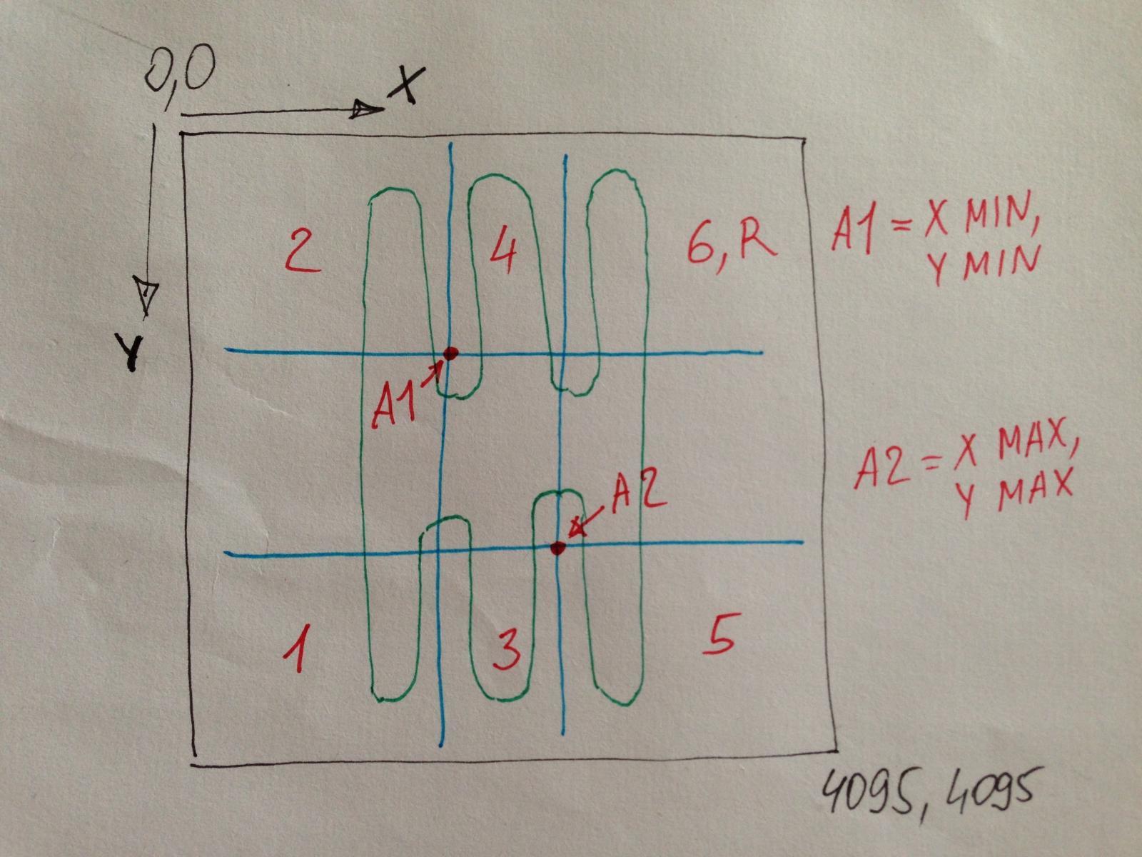 You can move blue lines by altering numbers in corresponding edit fields, hit Update button after each edit. Then check if shifter positions are detected correctly. Once you satisfied how shifter detects selected gear press Update and close SP_Profiler, values are stored in adapter flash memory.
Obtaining the board
PCB is available to order on kitnic.it. I'm testing data for 1clickBOM Chrome plugin to order all parts from major component suppliers (Digikey, Mouser, RS, Newark, Farnell). I'm also selling a small amount of the boards assembled manually by myself, contact me if you want one.
USB VID/PID
The board uses VID 0x1209 (InterBiometrics) / PID 0xF00D to identify itself, see pid.codes database.
License
This project is licensed under the BSD License - see the LICENSE file for details