A raspberry pi shield and software to communicate with FED devices
Buy Parts
| References | Qty | Description | Manufacturer | MPN | Mouser |
|---|---|---|---|---|---|
| J1,J2,J3,J4 | 4 | Audio Jack 3.5mm 3 pins | CUI | SJ1-3533NG | 490-SJ1-3533NG |
| J5 | 1 | RASPBERRY_PI_4B_+_Samtec_ | Samtec | ESQ-120-33-G-D | 200-ESQ12033GD |
| M1 | 1 | Fan connector PinHeader_1x02_P2.54mm | Harwin | M20-9750242 | 855-M20-9750242 |
FEDWatcher
FEDWatcher is sofware to connect up to 4 FED3 feeder devices to one Raspberry Pi 4. The Raspberry Pi communicates with the FED3 devices using software serial from the BNC/headphone jack port of the Adafruit feather into the activated UART channels on the Pi.
This repository contains:
- Python code that uses standard Raspberry Pi software and Python packages.
- The modified software serial library used on the FED3 devices. See softwareSerial.
- Files to print the PCB we are using as a Raspberry Pi HAT for easier interface with the Raspberry Pi 4 pinout.
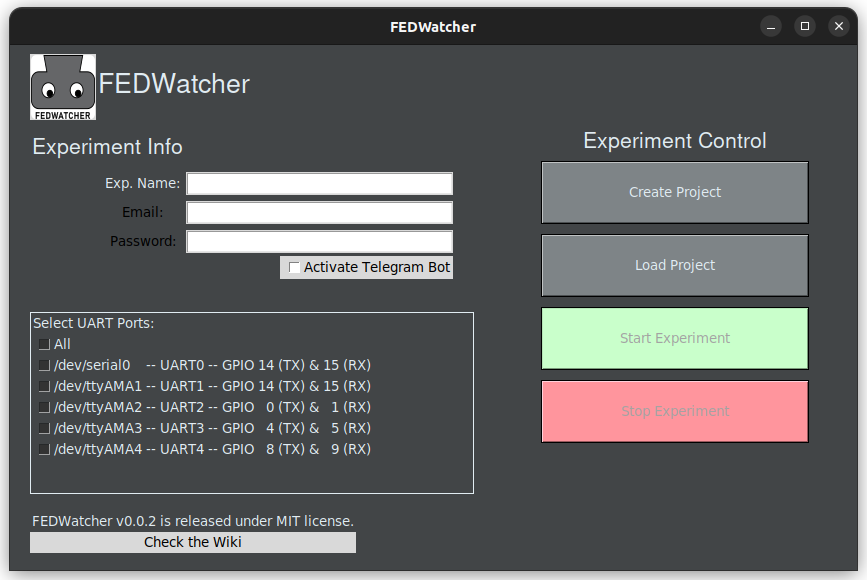
- Python code for FEDWatcher GUI, which provides a way for the user to create projects and trigger FEDWatcher easily (see pic below).
Installation
If you already have an OS installed in your Rasberry Pi, jump here. Otherwise continue reading.
To set up the Raspberry Pi, begin with flashing a standard image of Raspbian to an SD card. The project was coded and tested using Raspbian Lite with a Gnome Desktop and Raspbian Lite Buster, but any version of Raspbian should work.
For installing the operating system, the official Raspberry Pi Imager can be used. If you would like to install the Gnome desktop, the install will require that you have at least an 8GB SD card, the Pi plugged directly into a monitor, and a wifi or ethernet connection.
Gnome desktop
To use the Gnome desktop, first run
sudo raspi-config
Go into advanced options, select GL driver, install necessary packages if asked, and set the driver to fake KMS. Next, go back into advanced options and make sure you expand filesystem, as this is a large download. Then, back in bash, run
git clone https://github.com/TerraGitHuB/gnomeforpi.git && cd gnomeforpi && sudo bash gnomeforpi-install
This will take a long time. When the install is finished, the Raspberry Pi will reboot and you will be able to log into the Gnome desktop. In addition, the wifi will be disconnected, but you will be able to reconnect after logging in. After choosing your user and before entering your password, click the settings cog wheel under the password entry box and choose "Gnome for Xorg".
Edit config
Next, you must enable the four hardware UARTs within the Raspberry Pi. Navigate to /boot/ and edit config.txt however you prefer. This is an example using nano
sudo nano /boot/config.txt
[!TIP] In newer versions,
config.txthas been moved to/boot/firmware/config.txt. but everything else applies
At the end of the file, add on the following statements:
[spi0=on]
Settings when SPI0 is enabled: no uart4
No need to repeat uart2, uart3, uart5 if they are always loaded
[spi0=off]
Settings when SPI0 is disabled: include uart4
dtoverlay=uart4
[all]
dtoverlay=w1-gpio enable_uart=1 force_eeprom_read=0 disable_poe_fan=1 dtoverlay=uart2 dtoverlay=uart3 dtoverlay=uart5
The first two lines disable the GPIO 0 and 1 functionality to be used for uart2.

You can always remove/comment the first 3 lines above if you need to use a POE fan with the Pi at the same time, but it might create some unexpected erros. Please only do this if you are experienced with this type of config.

The general mapping to. As of now, FEDWatcher only uses RX ports, but the TX pins will be reserved too.
Below there's mapping between `uartx` -> `GPIOx` -> `board pin #`
uart GPIO Board Pins (function)
TXD RXD CTS RTS
uart0 14 15 8 10 uart1 14 15 8 10 uart2 0 1 2 3 27 28 (I2C) uart3 4 5 6 7 7 29 uart4 8 9 10 11 24 21 (SPI0) uart5 12 13 14 15 32 33 (gpio-fan)
You can also check the (UART pinouts here)[https://pinout.xyz/pinout/uart].

This configuration should work when connecting FEDs directly using jumper wires or when using the HAT we designed (see further below).

> [!IMPORTANT]
> Selecting proper pinout is key to correct functioning of the device. In general, FEDWatcher is flexible and works well with many HATs, but knowledge of the free/used pins is paramount for correct functionality.

Now, you will be able to clone the FEDWatcher github repository into your project and use the functions within it to run your own programs.

## fedwatcher python

To install the software itself, you are advised to use a virtual environment. Clone the repository and then install package requirements in the virtual environment. Installation in Raspberry Pi takes a long time, use the piwheel link in `pip3 install` to make it faster.

Using conda:
git clone https://github.com/matiasandina/FEDWatcher.git cd FEDWatcher
tested on python 3.7.3 and 3.10
conda create -n fw_env python==3.10 pip conda activate fw_env pip3 install -r requirements.txt --extra-index-url https://www.piwheels.org/simple
Using venv (please make sure you get a python version that is compatible!):
git clone https://github.com/matiasandina/FEDWatcher.git cd FEDWatcher python3 -m venv fedwatcher source fedwatcher/bin/activate pip3 install -r requirements.txt --extra-index-url https://www.piwheels.org/simple
To launch the GUI.
cd FEDWatcher/ source fedwatcher/bin/activate python3 fedwatcher/GUI.py
### Desktop entry

You can create a `FEDWatcher.desktop` file in the `Desktop` folder (e.g,. `nano /home/pi/Desktop/FEDWatcher.desktop`). The `Exec` will vary depending on how you installed FEDWatcher. Below, we reproduce an example compatible with the manual way and no virtual environment.
[Desktop Entry] Type=Application Comment=FEDWatcher Name=FEDWatchar Exec=python3 /home/pi/FEDWatcher/fedwatcher/GUI.py Icon=/home/pi/FEDWatcher/fedwatcher/img/64.png Terminal=true Categories=Utility StartupNotify=true
---
## Hardware

FED3 needs `.ino` sketches to be flashed into it. There are a few things that are crucial for fedwatcher to work properly in FED3 devices.

### Arduino side

On the Arduino side of things, you should have a few modifications to your sketch

Use
#include "FED3.h"
This will make use of a local `FED3.h` file, instead of the installed FED3 library. We are currently trying to work out a way to merge FEDWatcher into the common FED3 library but for the time being you will need to use a local file.


Use `setSerial(true)` to enable FEDWatcher.
void setup() { fed3.begin(); //Setup the FED3 hardware fed3.DisplayPokes = false; //Customize the DisplayPokes option to 'false' to not display the poke indicators fed3.timeout = 3; //Set a timeout period (in seconds) after each pellet is taken
// Turn to true if you are using FEDWatcher fed3.setSerial(true); }
You can check the `sampleSketch` folder which has a free feeding example with 3 second inter trial interval (time between pellets).
### Pinout
To connect the FED3 devices to the Raspberry Pi, you will need a cable that takes the BNC female from the FED3 (old version) or a 3.5 mm male jack to fit the 3.5 mm female jack (new version) and ends to interface with the Raspberry Pi (see below).
We have made custom cable using awg22 cable, BNC adapters, and male 3.5 mm jacks (see links below). If you are using the newer version of the FED3, any commercial stereo cable will work just fine.
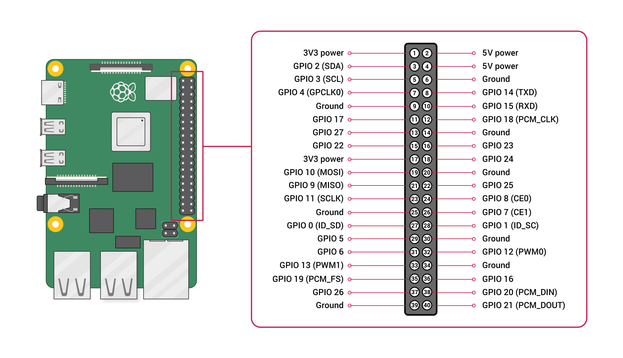
For this program, up to four FED3 devices can be hooked up to a single Raspberry Pi. There are four activated UART ports with receivers at GPIO pins 1, 5, 9, and 13, corresponding to port1, port2, port3, port 4, in order. The unused send pins are located at 0, 4, 8, and 12. **These pins cannot be used while this program is running**. However, if not all ports are used, they can be disabled in the setup function.
For this setup, the red/hot wire will go to one of the receiver post listed above, and the black/ground wire will go to any ground pin on the Raspberry Pi.
For more information on the pinout of the Raspberry pi visit the [Official Raspberry Documentation](https://www.raspberrypi.org/documentation/usage/gpio/). See below the official pinout for the Raspberry from the docs.
### Design of FEDWatcher HAT
We have also designed a little PCB board that sits on top of the RPi, so that it is easier for users to get started. This board was designed using KiCad 5.1 and
relies on the following libraries (for footprints and parts):
- https://componentsearchengine.com/part-view/RASPBERRY%20PI%204B%20%2B%20Samtec%20ESP-120-33-G-D/RASPBERRY-PI
Here's how the PCB looks like

There's a bit of soldering involved, but it makes things cleaner:
* Solder female pins to PCB to match Raspberry Pi's pinout.
* Solder female headphone jacks to PCB
* Solder male pins to match fan female connectors
These is how it looks like in our lab.


The designs live on the [hardware](https://github.com/matiasandina/FEDWatcher/tree/main/hardware/RPi_shield) folder in this repository, where you can also find the bill of materials for the HAT.
There are a few generic parts that we recommend using, but similar parts should work.
* [Heat Sink and Fan](https://www.amazon.com/GeeekPi-Raspberry-Cooling-Aluminum-Heatsink/dp/B07PCMTZHF/ref=sr_1_3?crid=Q8C55QA09LS2&keywords=raspberry+pi+fan+aluminum+heatsink&qid=1659374343&sprefix=raspberry+pi+fan+aluminum+heatsink%2Caps%2C65&sr=8-3)
* [BNC adapter](https://www.amazon.com/Connector-Coaxial-Terminal-Adpater-Surveillance/dp/B091Z1V55J/ref=sr_1_22_sspa?crid=16I3NQ8L51GTH&keywords=bnc+adapter+wire&qid=1659374513&sprefix=bnc+adapters+wire,aps,61&sr=8-22-spons&psc=1)
* [M2.5 brass standoff](https://www.amazon.com/HanTof-Raspberry-Standoffs-Standoff-Cylinder/dp/B07KM27KC6/ref=pd_sbs_5/136-6686908-1264224?pd_rd_w=xld4t&pf_rd_p=0f56f70f-21e6-4d11-bb4a-bcdb928a3c5a&pf_rd_r=T61GBPY4VQAJ1AG9K1SB&pd_rd_r=d5b09aac-2d40-4798-8f3f-64e0f1895e47&pd_rd_wg=2Fxwf&pd_rd_i=B07KM27KC6&psc=1)
## Contribute
This is a primary release, please file [issues](https://github.com/matiasandina/FEDWatcher/issues) to contribute to this project.